Hammond Road
Knowsley Industrial Park Liverpool
L33 7UL

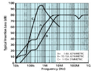
Insertion Loss in 50Ω system with or without load

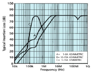
Insertion Loss in 0.1/100Ω system with or without load (0.1Ω at SMPS end)
A range of mains input filters for switched mode power supplies to prevent smps generated noise from getting back onto the mains.
| Rated Voltage | 250V ac 50/60Hz, 250Vdc | |
| Test Voltage | (line – earth) | 2250V dc |
| line – line) | 1250V dc | |
| Rated Current, IR | As tabulated | |
| Insertion Loss | See graph | |
| Maximum Volt Drop per line at full load dc current | 300mV | |
| Maximum Full Load Heat Dissipation | As tabulated | |
| Discharge Time to below 34V | 2s maximum | |
| Maximum Temperature Rise at Full Load | 25ºC | |
| Ambient Temperature Range | -25ºC to +85ºC | |
| Climatic Category | 25/85/21 | |
| Maximum Leakage Current (at 250V 50Hz) | 0.4mA | |
| Part Number | Current Rating IR (A) @50ºC* | Maximum Heat Dissipation (W) | Major Dimensions (mm) | Weight (g) | ||
|---|---|---|---|---|---|---|
| Length A | Width B | Depth C | ||||
| DS26760 | 1 | 0.3 | 64 | 56 | 38 | 275 |
| DS26761 | 3 | 2.5 | 64 | 56 | 38 | 275 |
| DS26762 | 6 | 3.5 | 88 | 60 | 38 | 445 |
| DS26763 | 10 | 3.0 | 112 | 76 | 38 | 750 |
| DS26764 | 15 | 6.5 | 112 | 76 | 38 | 750 |
*Current derating between 50ºC and 85ºCFor temperature, θ Iθ = IR ![]()

| Part Number | ||||||||||||||||
|---|---|---|---|---|---|---|---|---|---|---|---|---|---|---|---|---|
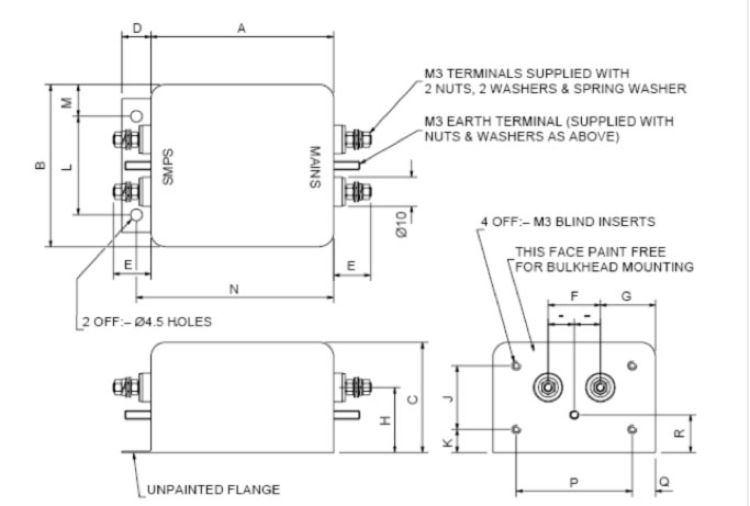
| A | B | C | D | E | F | G | H | J | K | L | M | N | P | Q | R | |
| DS26760, DS26761 | 64 | 56 | 38 | – | 13 | 18 | 19 | 25 | 22 | 7 | – | – | – | 40 | 8 | 12.5 |
| DS26762 | 88 | 60 | 38 | 11 | 13 | 20 | 20 | 25 | 20 | 9 | 35 | 12.5 | 94 | 44 | 8 | 12.5 |
| DS26763, DS26764 | 112 | 76 | 38 | 11 | 13 | 25 | 25.5 | 25 | 17 | 9 | 51 | 12.5 | 118 | 56 | 10 | 12.5 |
These filters should ideally be mounted through conductive metal bulkhead (unpainted but electroplated to prevent corrosion, if applicable). They should be fixed using 4 M3 screws of an appropriate length to suit the bulkhead thickness. This method of mounting will provide optimum high frequency filter performance. Larger filters are also provided with a mounting flange at the other end of the filter which should be secured with M4 screws. It is important that a good low impedance earth connection is obtained between the end of the filter and the bulkhead.
If bulkhead mounting is not used, the filter may be mounted using suitable brackets from the filter inserts, again ensuring that a good earth connection is made to the filter either via the mounting bracket or via the earth stud connection. Without bulkhead mounting, to maintain the high frequency performance of the filter, it is important to minimise by-pass coupling of the filter by using screened leads and by careful consideration of cable routing.
Bulkhead mounting is recommended to ensure the best high frequency performance is obtained. The quoted torque figures should be observed for the mounting inserts and the filter terminals. When making connections to the filter terminals, two spanners should be used to avoid applying excessive torque to the filter terminal studs.
In the case of SMPS filters, the end marked “SMPS” is the inductive end of the filter and should face the SMPS or low impedance. The other end marked “MAINS” (bulkhead mounting end) should face the higher impedance, (normally the mains). General purpose filters may be connected either way round.
It must always be ensured that a good low impedance earth connection is made to the filter
Terminals should be enclosed by the user, if required, for safety.
All high performance filters contain capacitors which will store charge even after the power has been removed from the filter. All ac filters listed in this catalogue are fitted with internal discharge resistor networks. These are intended to discharge the capacitors to a safe level within two seconds of switching off the power.
As an added precaution, after removing the power, filter terminals should always be shorted to earth (filter case) and to each other, before touching. A good low impedance earth connection must be made to the filter.