400Hz Filter Range
This range of filters has been specifically designed for use on 400Hz systems and utilises capacitors with low loss dielectric material to minimise heat dissipation. By using coupled choke designs, it has been possible to provide a good performance with comparatively low capacitance values and hence reactive current. However, it must be noted that at 400Hz, reactive current can be significant and this current has to be supplied by the generator as well as the load current.
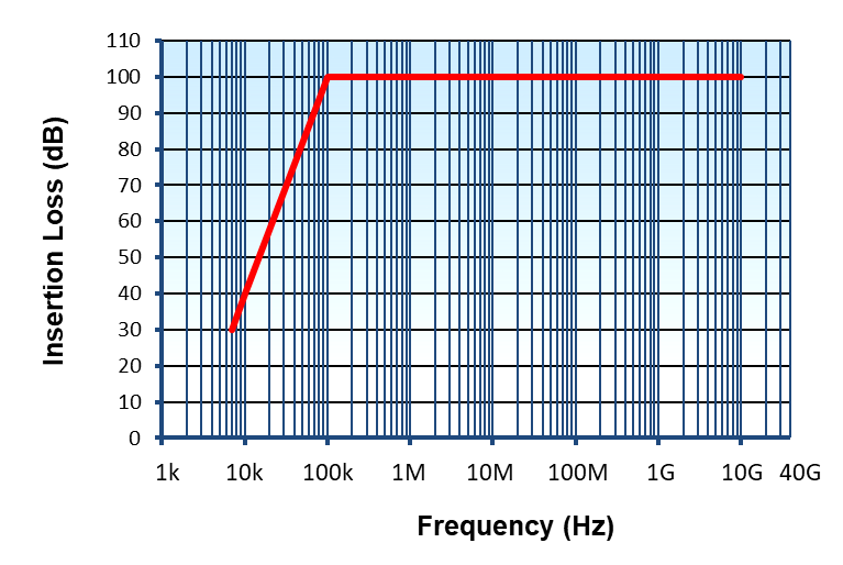
Insertion Loss Performance
Asymmetric attenuation shown as measured in 50Ω system, at all loading conditions, in accordance with CISPR-17.
Performance curve meets 100dB from 100kHz to 10GHz.
Typical Applications
- Military power supplies
- Aircraft ground power supplies
- 400Hz computer power supplies
- Supports compliance to MIL-STD-461 & DEF STAN 59-411
| Rated Current (A) | Part Number | DC Resistance (mΩ) | Earth Leakage (A) | Length (mm) | Width (mm) | Height (mm) | Approx. Weight (kg) |
|---|---|---|---|---|---|---|---|
| 32A | DS25902 | 15 | 1 | 550 | 205 | 95 | 16 |
| 63A | DS25903 | 10 | 1 | 550 | 205 | 105 | 20 |
| 100A | DS25904 | 5 | 1.8 | 640 | 205 | 120 | 22 |
| 200A | DS25905 | 2.5 | 7 | 660 | 475 | 135 | 60 |
| Rated Current (A) | Part Number | DC Resistance (mΩ) | Earth Leakage (A) | Length (mm) | Width (mm) | Height (mm) | Approx. Weight (kg) |
|---|---|---|---|---|---|---|---|
| 32A | DS23606 | 15 | 3.5 | 550 | 410 | 95 | 22 |
| 63A | DS23607 | 10 | 3.5 | 550 | 410 | 110 | 32 |
| 100A | DS23608 | 5 | 7 | 660 | 410 | 135 | 45 |
| 200A | DS25907 | 2.5 | 14 | 660 | 575 | 150 | 70 |
Rated Voltage
- SP&N: 115VAC 400Hz
- TP&N 200/115VAC 400Hz
Rated Current
- 6A to 200A (each individual line, see table)
Current Overload
- 10 x maximum rated current for 1 sec.
- 1.5 x max rated current for 10 minutes.
Discharge time
- Max. 30 seconds to below 34V (filter incorporates discharge resistors)
Temperature Rise
- 25°C case rise on full load
Storage Temperature Range
- -45°C to +85°C Storage
- -45°C to +50°C Working
MTBF
- >0.3 million hours (calculated using Mil Hdbk 217F)
Surge Suppression (optional)
- 150VAC at 100J (8/20μs)
- All filters can be supplied with an integral metal-oxide varistor, fitted between the input terminal and earth (case).
All MPE installation filters are tested using the test methods defined within the following standards and meet or exceed the relevant performance and/or safety criteria defined within these standards:
- Mil-F-15733
- Mil-Std-220C
- CISPR17:2011/BS EN 55017:2011
- UL1283
- LVD 2014/35/EU
- DEF-STAN 59-411/MIL-STD-461
- RoHS (2011/65/EU) & LVD (2014/35/EU)
- UKCA & CE
Ordering Code
DS XXXXX / X / X (e.g. DS23606CV)
- Filter Part Number
- Suffix C for standard cable entry (for other cable entries, see Installation Details page)
- Add suffix V for transient suppressed filter